
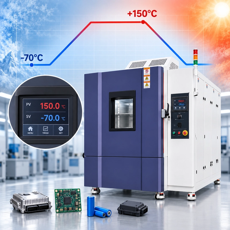
A typical rapid temperature change chamber inquiry might read:
“We need a 500 L chamber, −70°C to +150°C, 10°C/min.”
That sounds fairly specific. From an equipment-selection standpoint, however, several important pieces are still missing.
Where does the 10°C/min requirement apply? Is the same rate required during heating and cooling? Is it a controlled linear ramp or an average temperature change rate? What will be inside the chamber? How much does the DUT and fixture weigh? Will the DUT remain powered and generate heat?
There is another question that is easy to overlook:
Does the required temperature ramp rate apply to chamber air or to the DUT itself?
Two applications can both ask for a “10°C/min chamber” and place very different demands on the heating and refrigeration system.
So when choosing between 5°C/min, 10°C/min and 15°C/min, start with the test profile—not the chamber catalog.
What Does 10°C/min Actually Mean?
Temperature ramp rate describes how quickly temperature changes over time. It is normally expressed in °C/min or K/min.
The basic calculation is straightforward:
Temperature Ramp Rate = Temperature Change ÷ Time
Suppose the test moves from:
−40°C to +85°C
The total temperature difference is:
ΔT = 125°C
At an average rate of 10°C/min, the theoretical transition time is:
125°C ÷ 10°C/min = 12.5 minutes
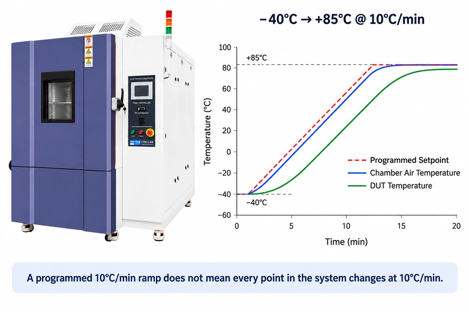
That calculation is useful, but it does not tell the whole story. During an actual test, three temperature responses need to be distinguished.
Programmed Setpoint
This is the temperature profile commanded by the controller. If the program specifies a linear 10°C/min ramp, the setpoint represents the target trajectory the chamber control system is trying to follow.
Chamber Air Temperature
This is the actual temperature response within the chamber workspace. It follows the programmed setpoint according to the chamber's heating, refrigeration, airflow and control capability.
DUT Temperature
The device under test has its own thermal response.
A PCB, aluminum enclosure, battery module and 50 kg mechanical assembly will not follow chamber air at the same rate. Mass, material, geometry, airflow, mounting method and internal heat generation all influence DUT temperature.
This distinction is fundamental:
A programmed 10°C/min ramp does not mean every point in the system changes at 10°C/min.
IEC 60068-3-5 addresses confirmation of temperature chamber performance and treats temperature rate of change as a chamber-performance characteristic measured under defined conditions. DUT thermal response is a separate part of the test problem.
5°C/min vs 10°C/min vs 15°C/min
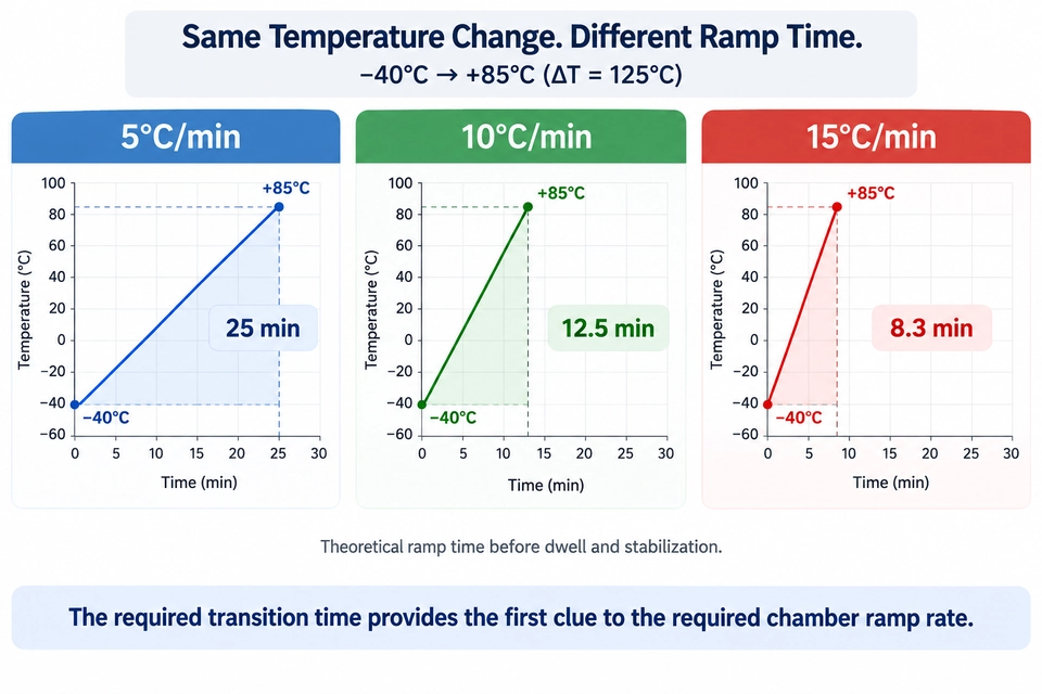
For the same temperature interval, increasing the ramp rate reduces the theoretical transition time.
Using −40°C to +85°C as an example:
| Requirement | 5°C/min | 10°C/min | 15°C/min |
|---|---|---|---|
| Temperature Change | 125°C | 125°C | 125°C |
| Theoretical Heating Ramp | 25 min | 12.5 min | 8.3 min |
| Heating + Cooling Ramp Portion* | 50 min | 25 min | 16.7 min |
| Thermal System Demand | Lower | Higher | Higher still |
| Influence of DUT Load | Important | More significant | Critical to verify |
| Loaded-Performance |
Recommended | Strongly recommended | Essential for demanding profiles |
*Assumes the same nominal rate in both directions. Dwell, stabilization and DUT thermal lag are excluded.
Looking only at this table, 15°C/min may appear to be the obvious choice. In practice, faster does not automatically mean better.
A faster ramp places greater demand on heating and refrigeration capacity. Depending on chamber size and configuration, it may also increase electrical demand, cooling requirements and equipment cost.
If the test only requires 5°C/min, buying substantially more ramp capability may add little value.
The opposite problem is more serious: if your test requires 10°C/min with the DUT installed, a chamber capable of 10°C/min only under a lighter or empty condition may not meet the actual test requirement.
The number is meaningful only when the conditions behind it are understood.
The Catalog Ramp Rate Is Only Half the Story
One of the most common RFQ problems we see is a temperature ramp requirement with no load information.
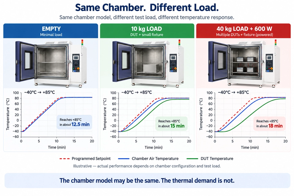
Consider a chamber specified as:
500 L · −70°C to +150°C · 10°C/min
Now consider two tests.
The first uses an almost empty workspace.
The second uses the same chamber with:
- 6 DUTs
- 28 kg total DUT mass
- 12 kg aluminum fixture
- cables and instrumentation
- 600 W active heat load
The chamber model has not changed. The thermal problem has.
This is the distinction that matters:
The catalog ramp rate tells you something about the chamber. The loaded ramp rate tells you whether it can run your test.
Why Thermal Mass Matters
Everything inside the chamber must gain or lose thermal energy during a transition.
The basic sensible-heat relationship is:
Q = m × cp × ΔT
where:
Q = thermal energy
m = mass
cp = specific heat capacity
ΔT = temperature change
This is not a chamber-sizing equation by itself. It simply explains why the load cannot be ignored.
A 2 kg electronic assembly and a 50 kg metal fixture may fit into the same workspace, but they create very different thermal demands.
As the required ramp rate increases, that difference becomes more important because the chamber has less time to transfer the required energy.
Powered DUTs Create a Different Load
Thermal mass and active heat generation are related to chamber performance, but they are not the same problem.
A 30 kg unpowered assembly stores and releases heat as its temperature changes.
A powered electronic product may simultaneously generate 500 W, 800 W or more while the chamber is trying to cool it.
During the cooling ramp, the refrigeration system must therefore deal with both the thermal energy being removed from the load and the heat that the DUT continues to generate.
For equipment selection, provide these separately:
Total DUT + fixture mass
Maximum live heat load
A DUT weight without its operating heat load can leave a large part of the cooling requirement undefined.
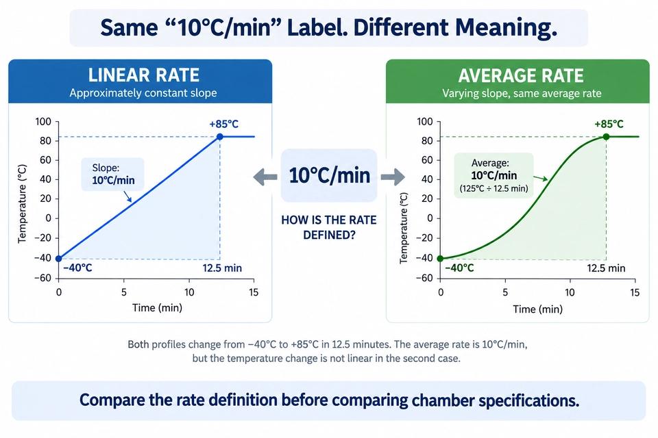
Linear vs Average Temperature Change Rate
A quotation stating:
Temperature change rate: 10°C/min
still leaves one important question:
How was the 10°C/min calculated?
A controlled linear ramp and an average temperature change rate do not necessarily describe the same performance.
With a linear ramp, the control system is programmed to follow a defined temperature slope through the transition. The aim is to maintain approximately the specified rate as the setpoint changes.
An average temperature change rate is calculated from the temperature difference divided by the measured transition time over a specified interval.
For example:
120°C ÷ 12 min = 10°C/min average
The chamber does not necessarily move at exactly 10°C/min during every part of those 12 minutes. One section may be faster and another slower.
IEC 60068-3-5 uses defined measurement conditions when confirming chamber temperature-change performance rather than assuming a constant rate over the entire chamber operating range.
From a purchasing standpoint, the practical rule is simple:
When a quotation says “10°C/min,” ask how the rate is defined and verified.
Also confirm the temperature interval, heating/cooling direction and applicable load condition before comparing two systems.
Chamber Temperature Range Is Not the Ramp-Rate Range
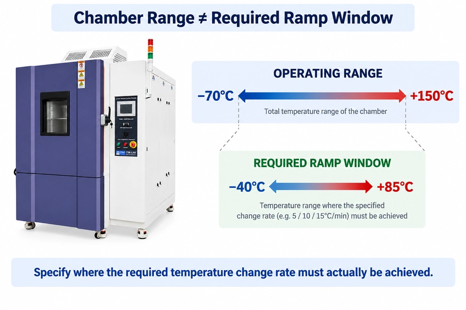
Suppose an environmental chamber is specified for:
−70°C to +150°C
and the same datasheet states:
15°C/min
It is easy to read those two numbers together and assume the chamber will perform a controlled 15°C/min transition from −70°C all the way to +150°C.
That assumption should not be made unless the performance is explicitly specified that way.
The operating temperature range describes the temperature limits within which the chamber can operate under specified conditions.
The ramp-rate range describes the temperature interval over which the stated rapid-change performance applies.
Those ranges do not necessarily have to be identical.
Heating and refrigeration capacity also change across the operating envelope. Cooling performance near the lower temperature limit, for example, can be more demanding than cooling through a region closer to ambient.
Instead of specifying only:
15°C/min, −70°C to +150°C
define the actual test:
Chamber operating range: −70°C to +150°C
Required test ramp: −40°C to +85°C
Heating: ≥10°C/min
Cooling: ≥10°C/min
Now there is a defined performance window that can be evaluated.
Heating Rate and Cooling Rate Need Separate Attention
Another common requirement is simply:
Ramp rate: 10°C/min
But does that mean 10°C/min in both directions?
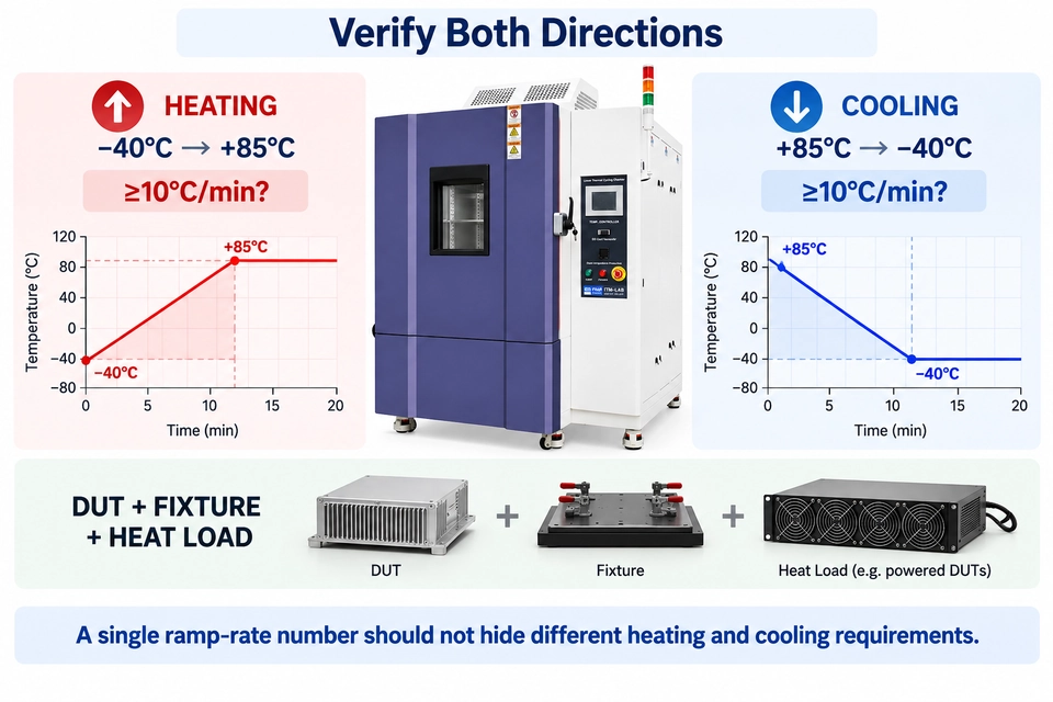
Heating and cooling place different demands on the chamber.
During heating, available heater capacity is a major factor. During cooling, the refrigeration system must remove heat from the workspace, DUT, fixture and any active heat-generating load.
For a demanding application, this is a much more useful requirement:
Heating: −40°C → +85°C, ≥10°C/min
Cooling: +85°C → −40°C, ≥10°C/min
DUT mass: 25 kg
Fixture mass: 10 kg
Live heat load: 500 W
Now the manufacturer can evaluate cooling performance against a defined thermal load rather than a single headline number.
This becomes particularly important at lower temperatures and when powered electronics remain active during the transition.
If your test depends on maintaining a specific rate in both directions, verify both directions separately.
How to Calculate Ramp Rate From Transition Time
Sometimes the test requirement does not specify °C/min at all.
Instead, it says:
Change from −40°C to +85°C within 15 minutes.
The temperature difference is:
85 − (−40) = 125°C
The theoretical average temperature ramp rate is therefore:
125°C ÷ 15 min = 8.33°C/min
That immediately tells us something useful.
A 5°C/min configuration cannot satisfy an 8.33°C/min theoretical chamber-air transition.
A 10°C/min-class system becomes the logical starting point for evaluation.
The word starting is important.
An 8.33°C/min calculation does not automatically mean:
Buy a 10°C/min chamber.
The next questions are still:
- Must the rate be achieved under load?
- Is it required during heating, cooling or both?
- What temperature window applies?
- Is the required rate linear or average?
- How much thermal mass is inside?
- Is the DUT generating heat?
The calculation narrows the equipment search. It does not complete the chamber selection.
Worked Example: −40°C to +85°C
Now compare all three ramp rates using the same profile.
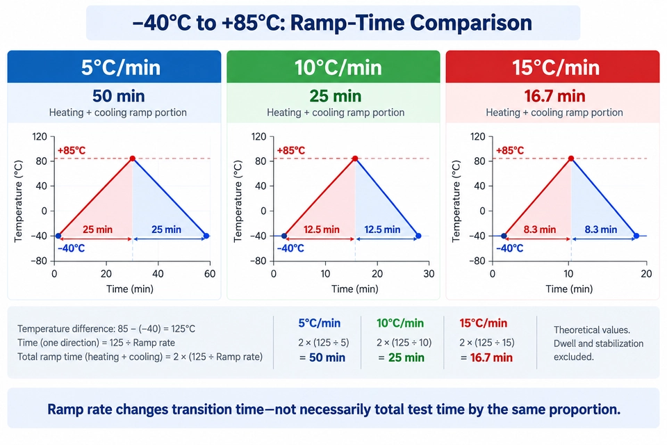
The temperature span is:
125°C
At 5°C/min, the theoretical heating transition takes:
125 ÷ 5 = 25 minutes
If cooling occurs at the same nominal rate, the heating and cooling ramp portions together require approximately:
50 minutes
At 10°C/min, those numbers fall to:
12.5 minutes heating
and:
25 minutes total heating + cooling ramp time
At 15°C/min, each theoretical transition takes approximately:
8.3 minutes
giving approximately:
16.7 minutes total ramp time
This can make a meaningful difference when a test runs dozens or hundreds of cycles.
But ramp time is still not cycle time.
A real profile may look more like:
Ramp → Stabilize → Dwell → Ramp → Stabilize → Dwell
There is also an important question about when dwell begins.
If dwell starts when chamber air reaches the target, the timing differs from a test that requires the DUT itself to reach a specified temperature before the dwell timer starts.
So increasing chamber ramp rate from 5°C/min to 10°C/min does not necessarily cut the entire test duration in half.
When Is 5°C/min Enough?
A 5°C/min temperature ramp rate can be entirely appropriate when the test calls for a moderate controlled transition.
It is worth considering when the required rate is 5°C/min or lower, when transition time is not the primary constraint, or when the DUT has substantial thermal inertia and would gain little from a much faster chamber-air transition.
There is no reason to treat 5°C/min as an entry-level or inferior choice.
If the test requires 5°C/min, it may simply be the correct configuration.
It is also worth remembering that not every hot/cold environmental test is a rapid temperature change test. A product that must be evaluated at −40°C and +85°C does not automatically require rapid cycling between those temperatures.
The test procedure decides that.
When Does 10°C/min Make Sense?
A 10°C/min temperature chamber becomes relevant when a 5°C/min system cannot meet the required transition time or when faster cycling has a meaningful effect on the test program.
It is often considered for faster thermal cycling and environmental stress screening-type applications, but that should not be turned into a universal rule.
ESS does not automatically mean 10°C/min.
The screening or reliability profile defines the required rate.
For example, if a customer specification requires −40°C to +85°C in approximately 15 minutes, the theoretical requirement is already 8.33°C/min. A 10°C/min-class chamber is therefore a sensible configuration to investigate.
Whether it can actually run the test still depends on loaded performance.
When Should You Consider 15°C/min?
A 15°C/min rapid temperature change chamber makes sense when the test genuinely requires the additional transition capability or when reducing ramp time has significant value to the test program.
At this level, load information becomes especially important.
The chamber may need to change its workspace temperature quickly while simultaneously transferring heat to or from a large DUT, fixture and powered load.
There is also no guarantee that the DUT itself will follow chamber air at 15°C/min.
A large assembly may respond much more slowly. Whether the resulting temperature differential is desirable depends on the purpose of the test.
The reason for choosing 15°C/min should therefore be:
“Our test requires this thermal environment.”
not simply:
“15°C/min is the fastest option.”
Don't Select Ramp Rate by Industry Alone
You may occasionally see simplified recommendations such as:
Electronics → 5°C/min
Automotive → 10°C/min
Aerospace → 15°C/min
They are convenient, but they are not a reliable basis for chamber selection.
An automotive controller can have a relatively slow qualification profile. A consumer electronics manufacturer can use a much faster screening cycle. Two aerospace components can have completely different thermal requirements.
Industry helps identify relevant standards and operating environments.
It does not determine temperature ramp rate by itself.
A better sequence is:
Product → Test Requirement → Temperature Profile → DUT Load → Chamber Configuration
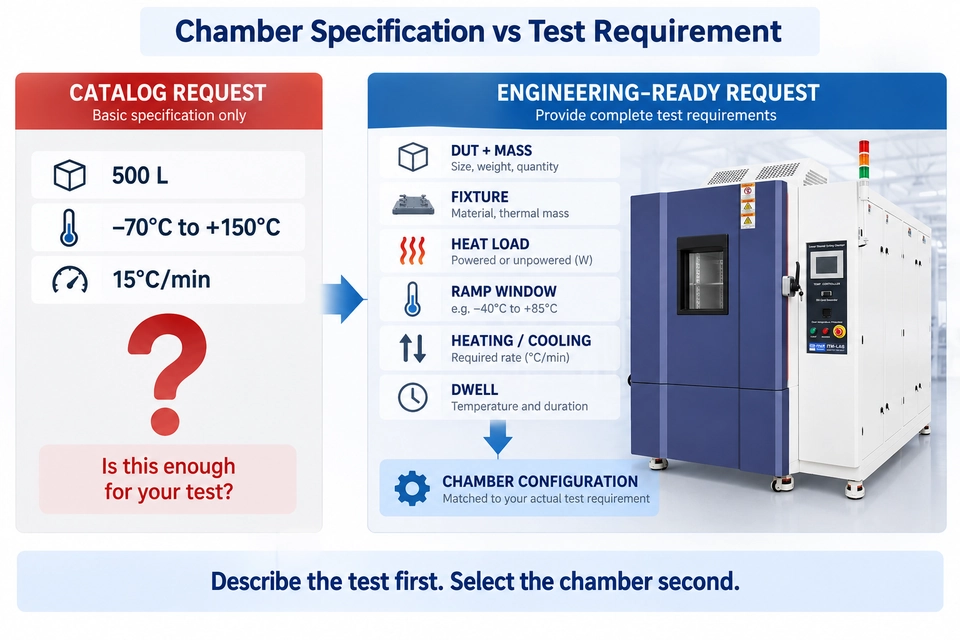
A Catalog Request vs an Engineering-Ready RFQ
This is where the difference becomes practical.
Suppose we receive:
500 L chamber
−70°C to +150°C
15°C/min
This gives us a useful starting point, but not enough information to verify the test.
Now compare it with:
DUT: 4 electronic modules
Total DUT mass: 32 kg
Fixture: 11 kg aluminum rack
Powered during test: Yes
Maximum live heat: 600 W
Required workspace: approximately 500 L
Chamber range: −70°C to +150°C
Actual test ramp: −40°C → +85°C
Heating: ≥10°C/min
Cooling: ≥10°C/min
Dwell: 30 minutes at each extreme
The second request gives the chamber manufacturer a test envelope that can actually be evaluated.
The second request describes a test. The first describes a catalog search.
That distinction can prevent both under-specification and unnecessary over-specification.
What Should You Include in a Rapid Temperature Change Chamber RFQ?
You do not need to perform the chamber manufacturer's thermal calculations yourself.
You do need to describe what the chamber will be asked to do.
| Requirement | Information to Provide |
|---|---|
| DUT | Product or component |
| DUT Dimensions | W × D × H |
| Quantity | Number tested simultaneously |
| DUT Mass | Total kg |
| Fixture / Rack | Material + approximate mass |
| Powered During Test | Yes / No |
| Live Heat Load | Maximum W |
| Chamber Range | Required minimum / maximum temperature |
| Actual Ramp Window | Start temperature → end temperature |
| Heating Rate | Required °C/min |
| Cooling Rate | Required °C/min |
| Rate Definition | Linear / average / specified method |
| Dwell Time | Required time at temperature |
| Humidity | Required / not required |
| Test Standard | Standard number or customer profile |
A DUT drawing, photo or fixture layout is also useful when loading arrangement, airflow or chamber workspace may affect the configuration.
Need Humidity Too?
If humidity is part of the test, do not assume the chamber can maintain its complete RH operating range throughout a 10°C/min or 15°C/min temperature transition.
Send the combined temperature + humidity profile for evaluation.
If humidity is required only during dwell periods, state that separately.
From the Test Requirement to an ITM-LAB KTB Configuration
The ITM-LAB KTB Rapid Temperature Change Test Chamber is designed for applications requiring controlled faster temperature transitions.
Available configurations include working volumes such as:
250 L / 500 L / 1000 L
temperature configurations reaching as low as:
−70°C
and rapid temperature change options including:
5°C/min / 10°C/min / 15°C/min
These should not be treated as three simple “good / better / best” equipment levels.
Consider this example:
DUT: Electronic control module
Quantity: 6
Total DUT mass: 24 kg
Live heat: 350 W
Profile: −40°C → +85°C
Required heating rate: 10°C/min
Required cooling rate: 10°C/min
It would be premature to stop at:
10°C/min requirement → select a 10°C/min KTB
The configuration still needs to account for the required workspace, fixture mass, loading arrangement, airflow and loaded heating/cooling performance.
This is particularly important when a powered DUT continues generating heat during the cooling transition.
For an actual KTB configuration, the useful inputs are:
DUT dimensions + quantity + DUT mass + fixture mass + heat load + low/high temperatures + ramp window + required heating/cooling rates
Those parameters describe the test the chamber needs to perform.
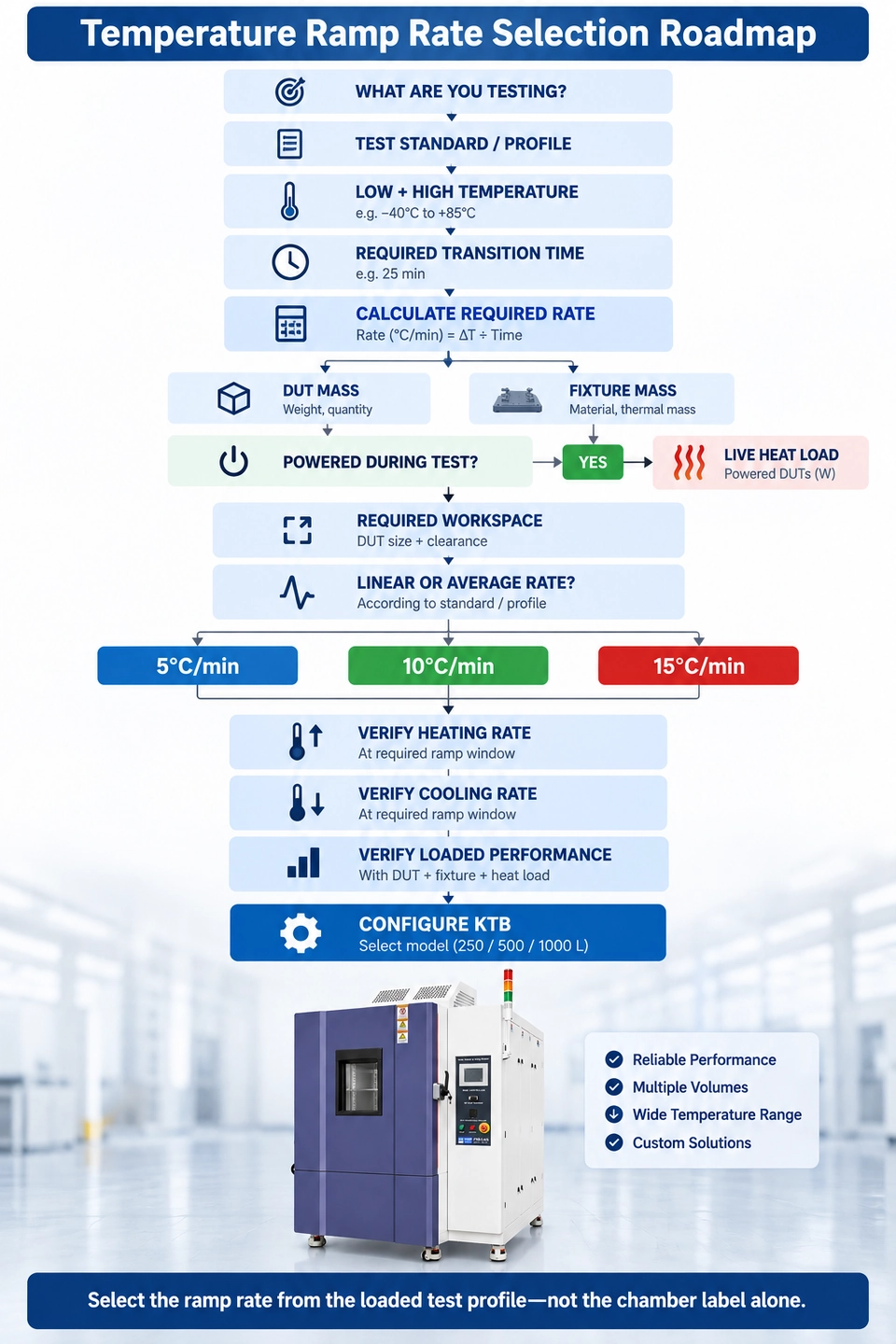
Temperature Ramp Rate Selection Roadmap
A practical selection sequence is:
WHAT ARE YOU TESTING?
↓
TEST STANDARD / CUSTOMER PROFILE
↓
LOW + HIGH TEMPERATURE
↓
REQUIRED TRANSITION TIME
↓
CALCULATE REQUIRED RAMP RATE
↓
DUT MASS
↓
FIXTURE MASS
↓
POWERED DURING TEST?
If yes:
LIVE HEAT LOAD
↓
REQUIRED WORKSPACE
↓
LINEAR OR AVERAGE RATE?
↓
Evaluate:
5°C/min / 10°C/min / 15°C/min
↓
VERIFY HEATING RATE
↓
VERIFY COOLING RATE
↓
VERIFY LOADED PERFORMANCE
↓
CONFIGURE THE CHAMBER
The order is deliberate:
Define the test first. Select the ramp rate second.
FAQ
What does 10°C/min mean on an environmental chamber?
It describes a temperature change rate under specified measurement and operating conditions. Before comparing chambers, confirm how the rate is defined, the temperature interval over which it applies, whether it refers to heating, cooling or both, and what load condition applies.
How long does it take to go from −40°C to +85°C at 10°C/min?
The temperature difference is 125°C.
The theoretical transition time is:
125°C ÷ 10°C/min = 12.5 minutes
This does not include stabilization, dwell or DUT thermal lag.
Does chamber ramp rate include the DUT?
Not necessarily. Chamber ramp specifications generally describe chamber temperature performance under defined conditions. DUT response depends on mass, material, geometry, airflow, mounting, fixture design and internal heat generation.
What is the difference between linear and average temperature change rate?
A linear ramp aims to follow a defined temperature slope through the transition. An average rate is calculated from the temperature change divided by transition time over a specified interval. Two chambers both described as 10°C/min may therefore require closer comparison before they can be considered equivalent.
Should I choose a 5°C/min, 10°C/min or 15°C/min chamber?
Start with the required test profile and transition time. Then account for the temperature window, DUT and fixture mass, active heat load, chamber workspace and loaded heating/cooling performance. The highest available ramp rate is not automatically the right choice.
Does DUT heat load affect cooling rate?
Yes. A powered DUT continuously adds heat that the refrigeration system must remove during cooling. If the DUT remains powered, include its maximum heat dissipation in watts when requesting a chamber configuration.
Before You Choose the Ramp Rate
The choice between 5°C/min, 10°C/min and 15°C/min should not begin with the chamber catalog.
Begin with the test.
Define the temperature window and transition time, then determine what the chamber will contain and whether that load generates heat. Specify heating and cooling separately when both directions matter, and confirm how the required rate is defined.
A 5°C/min chamber may be exactly right for one application. Another test may genuinely require 15°C/min. And two chambers carrying the same nominal 10°C/min specification may not provide the same usable performance once the actual DUT is installed.
The most useful question is therefore not:
“How fast is the chamber?”
It is:
“Can the chamber reproduce my required temperature profile with my actual test load?”
For an ITM-LAB KTB configuration, send us your DUT dimensions, quantity, total mass, fixture mass, live heat load, required workspace, low/high temperatures, transition time and required heating/cooling rates.
That gives us a test to configure around—not just a ramp-rate number.
